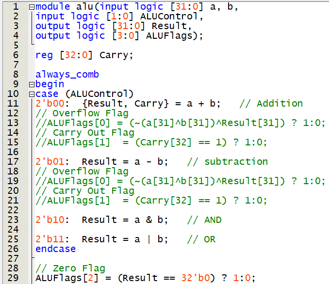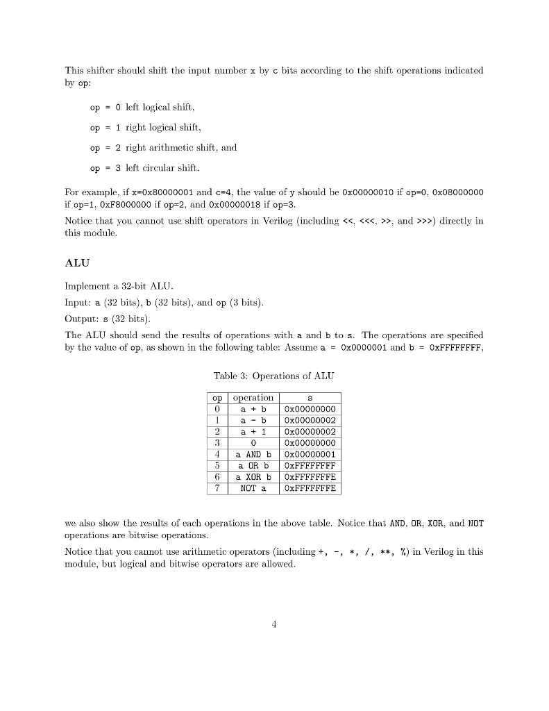

Introduction to clock concept => Synchronous designĬlock in FPGA (Field Programmable Gate Array) design is rather easy concept, since each flipflop is driven by a clock and FPGA is made up of many of such flipflops. (There will be a separate tutorial including the flag output in the ALU so stay tuned.) 3. but to keep things simple we will not introduce it in this tutorial. We also have a flag register which holds the different types of flags such as carry flag, zero flag, etc. Here, we have 16 instructions(8 arithmetic and 8 logical), so a 4-bit instruction bus is used. Thus in the given figure the A and B inputs are the 4-bit inputs, which work as the data supply for the ALU.Īnd secondly, we have Instructions that are necessary to tell the ALU which operation is to be performed with the operands. In order to understand the working of the ALU, we need to understand how do we talk to the ALU.įirst there is the data bus, through which we provide the data to be processed to the ALU. We will also use the parametric approach so that this design could be scaled up to the requirement of the designer. In this tutorial, we will build a 4-bit synchronous ALU using our very own Verilog HDL. This practice helps to keep the logic concise and easy to understand.


Many times the Logical and Arithmetic part is divided into two different parts. This unit, as the name suggest, helps in any arithmetic and logical operations that come across the processor. An ALU is the most basic part of any computer processor.


 0 kommentar(er)
